Introduction
Welcome! This is the homepage of Sa-TikZ, a TikZ library to draw Switching architectures.
The version v0.6 provides a way to draw Clos Networks Strictly-non-Blocking
(snb) and Rearrangeable (rear), Benes Networks and Banyan Networks (in particular Omega and Flip Networks); moreover, the package provides the possibility
to fully customize the aspect of the drawn network: the dimensions of module,
their distance and the font used are few examples. Finally, Sa-TikZ let the user
to draw connections among the stages by accessing the single ports of the modules.
Sa-TikZ is distributed under TeXLive and MiKTeX and it is part of the Comprehensive TeX Archive Network - CTAN.
The official CTAN page is http://www.ctan.org/pkg/sa-tikz: it provides
a link to download the documentation, also accessible typing in a terminal texdoc sa-tikz.
How to contact the author
To contact me for feature requests or problems you can send me an e-mail.
Please, if you have problems try to produce a minimal working example (MWE): this helps in understanding more quickly the issue and to give you a faster answer.
Examples
Simple examples of Clos Networks
Clos Networks could be Strictly Non Blocking or Rearrangeable. Sa-TikZ allows to draw them in both modes
by computing automatically the constraints that define a Clos Network to belong to a given type.
In the first example it is shown a Clos Network Strictly Non Blocking 8x10 with modules 2x2 for the first and the last stage.
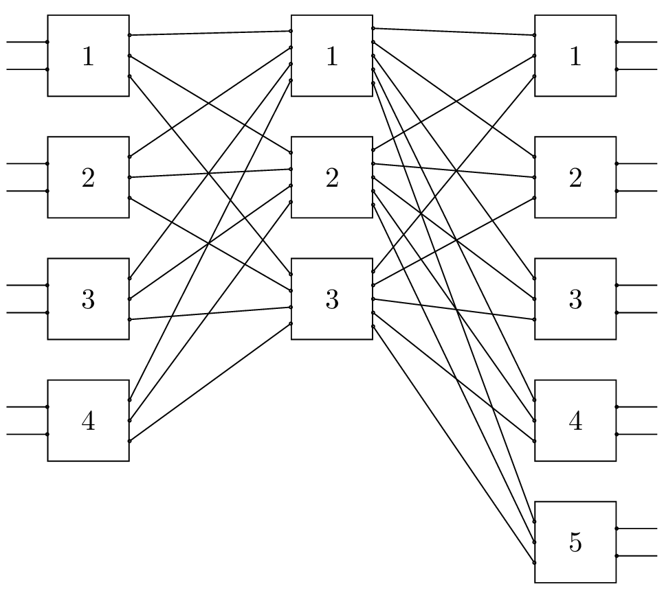
The code:
\documentclass{article}
\usetikzlibrary{switching-architectures}

\begin{document}
\begin{tikzpicture}
 \node[N=8, r1=4, M=10, clos snb] {};
\end{tikzpicture}
\end{document}
The same Clos Network 8x10 with modules 2x2 for the first and the last stage is now drawn in order to be Rearrangeable.
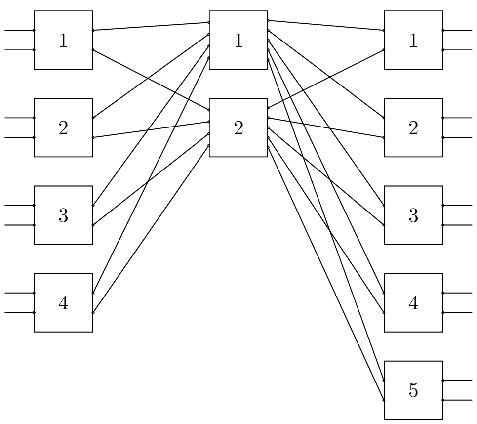
The code:
\documentclass{article}
\usetikzlibrary{switching-architectures}

\begin{document}
\begin{tikzpicture}
 \node[N=8, r1=4, M=10, clos rear] {};
\end{tikzpicture}
\end{document}
A simple example of Benes Networks
This example represents a Benes Network 32x32 drawn in its whole completexity.
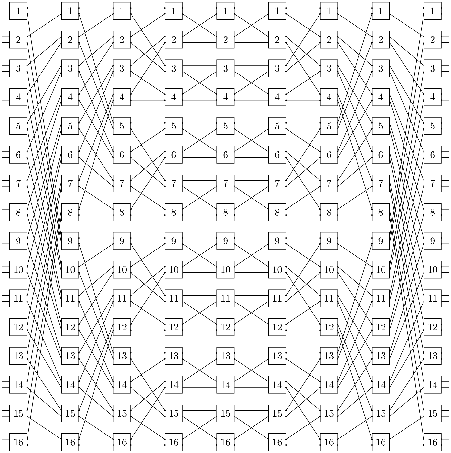
The code:
\documentclass{article}
\usetikzlibrary{switching-architectures}

\begin{document}
\begin{tikzpicture}[
 module size=0.6cm,
 pin length factor=0.5,
 module ysep=1]
 \node[P=32,benes complete] {};
\end{tikzpicture}
\end{document}
An advanced example
This advanced example shows a possible configuration of a Benes Network step by step in a presentation. Notice how in the left column it is shown the next built path before it is drawn in the network: this could be done using in the proper way the instruments provided by Beamer.
The code:
\documentclass{beamer}
\usepackage{lmodern}
\usepackage{tikz}
\usetikzlibrary{switching-architectures} % http://www.ctan.org/pkg/sa-tikz

\newcounter{port}

% legend image
\newcommand{\leg}[1]{%
  \tikz[baseline=-0.5ex]\draw[#1,ultra thick](0,0)--(1.5em,0);
}

% arrow
\newcommand{\tikzarrow}[1]{%
  \tikz[baseline=-0.5ex]\draw[-stealth](0,0)--(0.75em,0);
}

% connection description
\newcommand{\mydescription}[3]{%
  \item<+->[\leg{#1}] in #2 \tikzarrow\ out #3
}

\begin{document}
\begin{frame}{A Benes Network: a possible configuration}
\begin{columns}[T]
% The network
\begin{column}{0.7\textwidth}%
\centering
% Style to customize the module's aspect
\tikzset{module size definition/.style={
  module size=0.75cm,
  pin length factor=0.75,
  module xsep=2.25,
  module ysep=1.25,
  }
}
\begin{tikzpicture}[scale=0.9,transform shape]
\node[module size definition,benes complete={module label opacity=0}] {};
% Labels
% * * *
% input
\setcounter{port}{0}
\foreach \startmodule in {1,...,4}{
  \foreach \port in {1,...,2}{
    \stepcounter{port}
    \node[left,font=\tiny] at (r1-\startmodule-front input-\port)
     {in~\theport};
  }
}
% * * *
% output
\setcounter{port}{0}
\foreach \startmodule in {1,...,4}{
  \foreach \port in {1,...,2}{
    \stepcounter{port}
    \node[right,font=\tiny] at (r5-\startmodule-front output-\port)
     {out~\theport};
  }
}
% * * *
% Connections
% overlay starts with 2 such that the newtork is empty at the beginning
\draw<2->[red,ultra thick](r1-2-input-1)--(r1-2-output-2)--
 (r2-3-input-2)--(r2-3-output-1)--
 (r3-3-input-1)--(r3-3-output-2)--
 (r4-4-input-1)--(r4-4-output-1)--
 (r5-3-input-2)--(r5-3-output-2);
\draw<3->[blue,ultra thick](r1-4-input-1)--(r1-4-output-1)--
 (r2-2-input-2)--(r2-2-output-1)--
 (r3-1-input-2)--(r3-1-output-1)--
 (r4-1-input-1)--(r4-1-output-1)--
 (r5-1-input-1)--(r5-1-output-2);
\draw<4->[orange,ultra thick](r1-4-input-2)--(r1-4-output-2)--
 (r2-4-input-2)--(r2-4-output-1)--
 (r3-3-input-2)--(r3-3-output-1)--
 (r4-3-input-1)--(r4-3-output-2)--
 (r5-2-input-2)--(r5-2-output-2);
\draw<5->[green!50!black,ultra thick](r1-3-input-2)--(r1-3-output-2)--
 (r2-4-input-1)--(r2-4-output-2)--
 (r3-4-input-2)--(r3-4-output-1)--
 (r4-3-input-2)--(r4-3-output-1)--
 (r5-1-input-2)--(r5-1-output-1);
\draw<6->[violet!70,ultra thick](r1-1-input-2)--(r1-1-output-2)--
 (r2-3-input-1)--(r2-3-output-2)--
 (r3-4-input-1)--(r3-4-output-2)--
 (r4-4-input-2)--(r4-4-output-2)--
 (r5-4-input-2)--(r5-4-output-2);
\draw<7->[blue!50!cyan,ultra thick](r1-3-input-1)--(r1-3-output-1)--
 (r2-2-input-1)--(r2-2-output-2)--
 (r3-2-input-2)--(r3-2-output-2)--
 (r4-2-input-2)--(r4-2-output-1)--
 (r5-3-input-1)--(r5-3-output-1);
\draw<8->[brown,ultra thick](r1-2-input-2)--(r1-2-output-1)--
 (r2-1-input-2)--(r2-1-output-1)--
 (r3-1-input-1)--(r3-1-output-2)--
 (r4-2-input-1)--(r4-2-output-2)--
 (r5-4-input-1)--(r5-4-output-1);
\draw<9->[gray,ultra thick](r1-1-input-1)--(r1-1-output-1)--
 (r2-1-input-1)--(r2-1-output-2)--
 (r3-2-input-1)--(r3-2-output-1)--
 (r4-1-input-2)--(r4-1-output-2)--
 (r5-2-input-1)--(r5-2-output-1);
\end{tikzpicture}
\end{column}
% avoids to much space between columns
\hspace*{-4em}
% Column with connections: they are displayed one frame
% before being drawn
\begin{column}{0.35\textwidth}%
\raggedleft
Connections
\begin{description}
\scriptsize
\mydescription{red}{3}{6}
\mydescription{blue}{7}{2}
\mydescription{orange}{8}{4}
\mydescription{green!50!black}{6}{1}
\mydescription{violet!70}{2}{8}
\mydescription{blue!50!cyan}{5}{5}
\mydescription{brown}{4}{7}
\mydescription{gray}{1}{3}
\end{description}
\end{column}
\end{columns}
\end{frame}
\end{document}